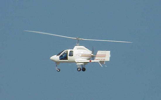
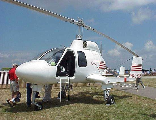
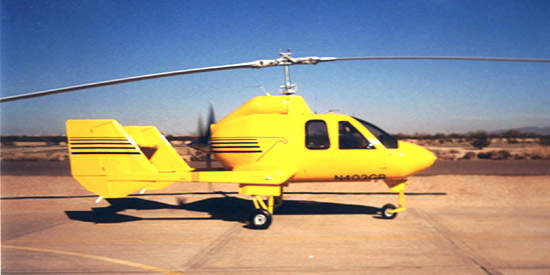
The Hawk 4 Gyroplanes will be the first in a series of specially designed and constructed aircraft by Groen Brother Aviation (BGA) based in Utah, USA. The Hawk 4 provides S/VTOL capabilities with its patented variable pitch rotor head and offers a safe and economic alternative for the rotor-craft and fixed wing market.
The first test flight took place in 2000 as part of the flight test programme underway at Groen Brother’s operations facility in Buckeye, Arizona. The FAA type certification process of the Hawk 4 began in 1998 but was abandoned in October 2001 due to a lack of available financing and the status of the programme is now uncertain.
Advanced Technologies Incorporated (Virginia) manufactured the two prototype blades, each measuring 42ft.
The Hawk 4 is powered by a 420 shp Rolls-Royce Model 250 series gas turbine engine. The design specifications for the airfoils were determined from rotor-performance calculations produced by the Department of Aerospace, Pennsylvania State University.
GYROPLANES
Gyroplane is an official term designated by the Federal Aviation Administration (FAA) describing an aircraft that gets lift from a freely turning tilted rotary wing (rotor blades), and which derives its thrust from an engine-driven propeller.
Gyroplanes in flight are always in autorotation. If power fails in a gyroplane the autorotation continues, and the aircraft settles softly to the ground from any altitude. The procedure to land after a power failure is the same procedure as a normal landing, which requires no landing roll. The single attraction of helicopters over gyroplanes is their ability to hover, which is necessary in some situations such as rescue, or in sling load work, air surveillance and point-to-point flying.
FUSELAGE
Constructed primarily by hand, the fuselage of the Hawk is a stressed-skin semi- monocoque (one-shelled) construction. The structural parts of the Hawk fuselage are constructed out of aluminum spars, ribs and skin. Spars are usually made of a thin plate, while ribs and skin are made of sheet. The curved parts of the Hawk 4 are non-structural fairings. These are designed to connect smoothly with the aluminum structure and provide a minimally disturbed air flow around the fuselage. The Hawk’s nose, engine cowling, and wingtips are made of composites, and the windshield and door bubbles are formed in heated ovens from acrylic sheet.
AIRFOILS FOR A GYROPLANE ROTOR
The design of the airfoils has been a continual learning process for the technicians at Groen Brother. The first objective was to achieve a high maximum lift coefficient for the Hawk 4. The second objective was to obtain low profile-drag coefficients over a wide range of lift coefficients.
Two major constraints were placed on the designs. First, the absolute value of the zero-lift pitching-moment coefficient must be no greater than a certain limit. Second, the airfoils must have certain thicknesses to satisfy structural requirements and t o provide sufficient volume for tip weights.
The design of the airfoils was complicated by the different operating conditions that will be faced by the Hawk 4. Specifically, the local flow should remain subsonic for all operating conditions.
The theoretical results show that the two primary objectives of a high maximum lift coefficient, insensitive to leading-edge roughness, and low profile-drag coefficients have been achieved. The constraints on the zero-lift pitching-moment coefficient and the airfoil thicknesses have been satisfied. Comparisons with other airfoils typically used on rotor blades illustrate the higher maximum lift coefficient and the lower profile-drag coefficients, thus confirming the achievement of the design objectives.


